Horn Loudspeaker
21st December 2003
Basic Study - Page 5 - Reverse Rubber Results
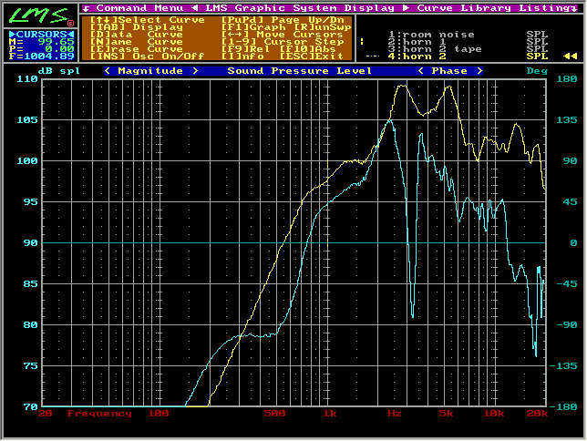
Notice the overall sensitivity level is dropped. This must be caused by the voice coil position off-set.
The lost of low freuqency is NOT evident in this case because the voice coil position off-set is more significant in this case.
Lost of high frequency is prominent. This trade off is not acceptable - at this level. Must be due to the voice coil position error.
The dip at 3.2kHz -25dB is probably due to the front chamber phase canceling with the phase plug.
Notice the the yellow curve from 5kHz to 20kHz - traced and retarded into the blue curve from 3.5kHz to 20kHz. This is due to the phase plug effect. Phase plug are put in to further extend compression driver's frequency range. Please remember to see Phase Plug later on.
However it is known that the total sound output is not the compression driver alone therefore a further study coupled with the horn will be required in the future.
ACOUSTICS SECTION AUDIO SECTION CAR SECTION
HOME - Technical Website for Acoustics, Audio and Car
 Malaysia
Boleh
Malaysia
Boleh