Horn Loudspeaker
21st December 2003
Basic Study - Page 4 - Reverse Rubber Process
Just for investigation purposes, the rear rubber will be placed at the front. This off-set will make rear chamber air volume smaller, which from theoretical study indicates lack of low frequency.
As always with nature is that all forces are balance, hence the lack of low frequency will only produce a by-product of extra high frequencies. Lets see: -
Nearly forgot to mention, the off-set will also cause the voice coil position to be different and the magnet flux interaction will be different. Please note.
The process: -
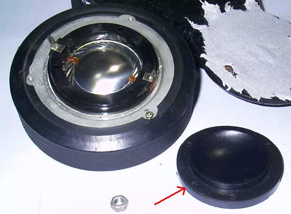
The back cover is open. Notice the red arrow in the picture trying to show the rubber.
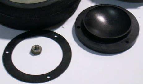 The rubber like
a ring
The rubber like
a ring
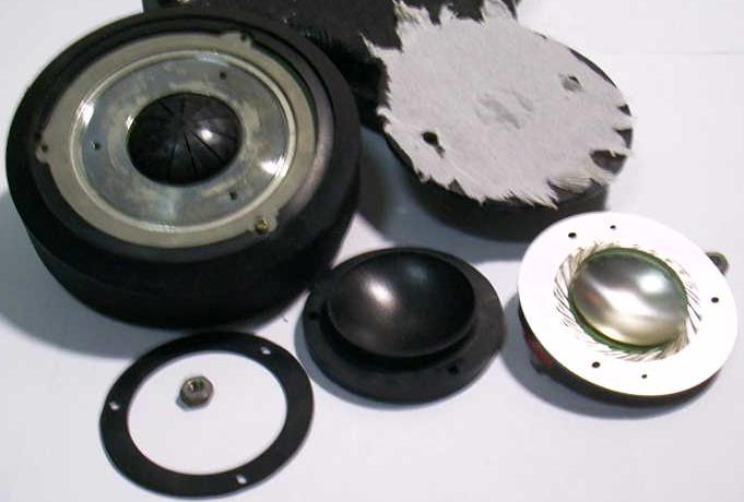
Finally the voice coil is taken out.
So now, instead of putting the rubber between the voice coil and the cover. It will be placed between the body and the voice coil. Please see two example below.
 or
or 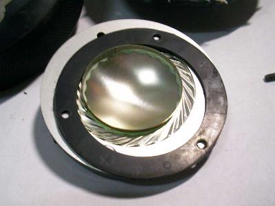
The voice coil diameter is approximately 45 mm and including the suspension is approximately 57 mm.
ACOUSTICS SECTION AUDIO SECTION CAR SECTION
HOME - Technical Website for Acoustics, Audio and Car
 Malaysia
Boleh
Malaysia
Boleh