So: -
AFM Repair Successful
Part 4 - 18th November 2003 (Tuesday)
Morning
Start the car but idle bad. Give up and go to work.
Evening - Session 1
2000 hours finish watching Korean soap TV (hehehe) and try to start with a dry??? AFM but failed.
Measure the AFM Flap's out and found 0.5xxV to 0.2xxV. At
last better than last night. Now it starts to have the symptoms of reducing
voltage like 5V to 0V. There is hope!!!!!
Take AFM out and spray with contact cleaner alcohol kau kau until like flooded and quickly shake off and wipe with tissue. Install and start,
still failed :(
Aiyah, why so mafan (troublesome) one??? :(
Give up - try the special project!!!
Special Project = Replace AFM by MAP plus Signal Converter - click to view story
This is hoped to run AFM-less ![]() During the purchase
of the MAP sensor, a turbo pressure sensor was bought instead. This mistake was
only later discovered when pointed out by a friend (Chin Lee Kun). Hahahaha,
what an idiot
During the purchase
of the MAP sensor, a turbo pressure sensor was bought instead. This mistake was
only later discovered when pointed out by a friend (Chin Lee Kun). Hahahaha,
what an idiot ![]() just because it looks like a MAP sensor so it was taken.
Hahahahah
just because it looks like a MAP sensor so it was taken.
Hahahahah
So: -
take out spare AFM's 7 pin socket
solder on turbo pressure sensor
solder on signal convertor
solder on air intake temperature sensor
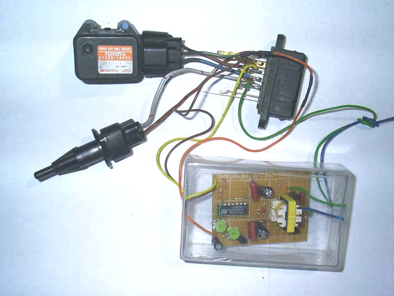
woahla - install - start ![]() wah can idle wor
wah can idle wor ![]() hahahaha
hahahaha
But signal convertor off-set potentiometer need to set to 2.5V and gain
potentiometer to match.
When set to 3.1 volt like AFM for idle cannot :( engine die.
Anyway, at least this test proves that the wire from AFM socket back to ECU is
OK. The one PIN name VS (which is the AFM Flap's signal from AFM to ECU).
Wah, so near to running open trumpet ![]()
![]()
![]() . Can idle, Can rev, but CANNOT maintain
rev :( (i.e. cannot partial throttle hold)
. Can idle, Can rev, but CANNOT maintain
rev :( (i.e. cannot partial throttle hold)
Anyway, give up, clean up and rest. To find out the reason why it failed, please
see
Session 2
0000 hours Mr.
Wong Yee Yong (Levin818) came around and we went to mamak
(non alcoholic drinks).
After go back home Mr. Wong Yee Yong (Levin818)
took a serious close up look at the AFM and found that something on the circuit board is
different / dirty / missing / gone. Use the
multi meter to check and found discontinuity.
The severed area cannot be seen so a exaggerated picture will be shown instead.
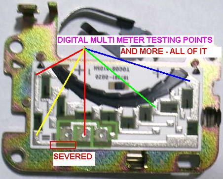
What happen now is that there is supply voltage VC = 5V+ DC, but only reached the connector, once go to the circuit board -
it is severed :( - it is no wonder why the AFM Flaps' output voltage is so low.
There is simply no voltage for the FLAP (pin VS) to send back to the ECU, cause there was no actual supply of the 5V+ DC called VC.
Anyway, a repair was attempted by soldering on a jumper wire to force 5V+ DC called VC back onto track and tested it.
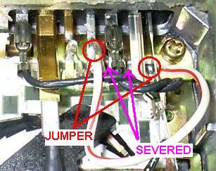
Woahla - start the car - choke choke choke idlesssssssssssssssssssssssss
Done. What an experience??? What a lucky day. Thanks to Mr.
Wong Yee Yong (Levin818), yolk and my
mechanic.
From this incident - we learn
1) yolk's FXGT 20v is different from ordinary - extra 4 pins in diagnostic plug and his ECU will register error code 21, while my ecu on his did not register error 21????
2) yolk's 20vAFM will start and idle at 900 rpm when ECU is newly installed without run-in - while mine always shoot up to 1,600 rpm - need to drive 20km rev kau kau 8,000 rpm a few times, 4,000 rpm allot then will run-in. Need allot full throttle even without increasing speed, just so the ECU really knows where is idle throttle and where is full. I suspect also need to let the water temperature go into HIGH HOT, so it will knows everything more accurately for run-in. :(
3) proper diagnostic means actually measuring the voltage in the AFM until the final final point, not just the connectors - hahaha - my mistake :(
4) my 20vAFM always need to idle at 1,600 at first - that's why when install the Turbo Pressure sensor + signal convertor cannot idle at 3.1 volt.
So why did that area on the circuit is burned??? gone???
 Malaysia
Boleh
Malaysia
Boleh