Replace AFM by MAP
18th November 2003 Midnight (I can't sleep thinking)
Special Project - Use MAP + signal converter to replace AFM without changing original L-jetronic ECU.
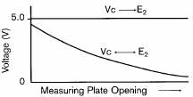
From http://www.autoshop101.com/forms/h34.pdf it is known that AFM produce theoretically 4V to 0.3V from small air volume intake at low revs to high air volume at high revs. It is represented by the following graph from file h34.pdf: -
So, upon key "ON" the flap voltage will feedback 4V to the ECU to confirm AFM's functioning, then idle at around 3.1V or 3.2V and finally max flap deflection at around 0.3V.
0.6xxxV was previously registered using a digital multi meter on Toyota 4AGE 20v AFM (silvertop) at approximately 8,000 rpm
A MAP sensor however does the opposite, taken from file http://www.autoshop101.com/forms/h35.pdf: -
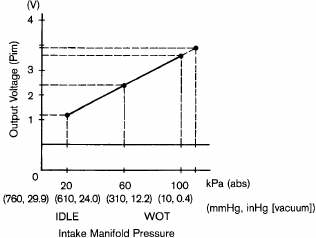
Both graphs looks similar except they are going the opposite way and that one is linear while the other is logarithmic.
So, how to change the 20v_AFM into a 20v_MAP?
Hmmmmm, no big deal. All it is needed is a electronic converter to pick-up the MAP sensor's signal and invert it as in 0V to 5V and come out as 5V to 0V.
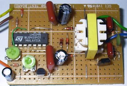
A prototype circuit has been made (back in July 2003) by a electronic friend (thank you Mr. Chong). It inverts signal analogously between 5V range. Has a output limiter set at 6.3V (Chong's idea). It has a gain pot (to increase or decrease signal - for the purpose to idling matching) and finally a bias pot (think of it as to increase or decrease the curve angle). Pretty neat as a prototype.
Due to the following incidents: -
The testing of this prototype / idea is called for.
At this point it is known that this idea will not work fully. The gain off-set capability will surely help make sure the car manages to start and maintain a proper idle.
However it is the revving or holding partial throttle that is in serious question / doubt. Because the MAP sensor's graph was only recently understood more properly after reading: - How to Diagnose your Engine using Vacuum Gauge. (please read it)
To make the story short. Map sensor measures Vacuum, not air flow and the vacuum in a engine behaves like this: -
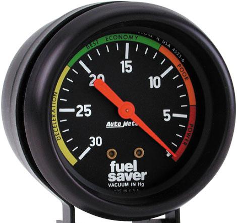
On idle it will be around 20 IN Hg (inches mercury). During acceleration it will increase towards 0 IN Hg. At full throttle it will be either exactly or extremely close to 0 IN Hg on extremely healthy engines.
After desired speed is achieve the vacuum will increase from the O IN Hg full throttle back to around 20 IN Hg.
During deceleration it will go towards 30 IN Hg. Full vacuum.
This is completely different to a AFM, because AFM actually measures total amount of air volume passing through the passage by the flap. Theoretically the higher the rpm the more air it requires and hence flap open more.
Both principal is completely different, perhaps this is why two different EFI principal are created. Namely L-jetronic mated with the AFM and D-jetronic matched with the MAP.
Both L-jet and D-jet EFI system is not fully known or understood at this time.
OK, now that the engine's breathing is understood a little better therefore it is known that this idea will not work. But since it is made, lets not waste the final actual practical testing of the prototype / idea.
During the purchase of the MAP sensor, a turbo pressure sensor was bought instead. This mistake was only later discovered when pointed out by a friend (Chin Lee Kun). Hahahaha, what an idiot :) just because it looks like a MAP sensor so it was taken. Hahahahah
Turbo pressure sensor's output voltage: -

If you look carefully at the boost readings. MAP reads from 30 IN Hg to 0 IN Hg, while this turbo pressure sensor reads from 0 IN Hg to 60 IN Hg. So another foul up here which will cause this idea not work.
I think: -
30 IN Hg = -15 psi (minus) = minus 1 bar
0 IN Hg = 0 psi ???
60 IN Hg = 30 psi = positive 2 bar
So: -
take out spare AFM's 7 pin socket
solder on turbo pressure sensor (supposed to be vacuum sensor)
solder on signal converter
solder on air intake temperature sensor
On the socket of the AFM (viewed in the following picture from right to left): -
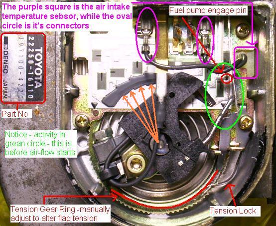
Pin 1 and 2 is the fuel pump engage pin and can be ignored. Just remember not to leave the key in the ON position too long without actually starting the car, because not only does the ECU consumes power, so will the fuel pump now.
Pin 3 an 5 is signal ground, namely E2 in the ECU and is used for air intake temperature sensor's ground, AFM Flap's feedback ground - now used for turbo pressure sensor's ground (supposed to be vacuum sensor) and signal converter's ground.
Pin 4 is VC in the ECU, which is the 5V+ DC regulated power supply. This will be used to power the turbo pressure sensor.
Pin 6 is VS in the ECU, used to be for the AFM Flap's output voltage to the ECU. Now will be used for the signal converter's output voltage.
Pin 7 is air intake temperature sensor's voltage / signal. This is actually only a thermo-resistor and does not have polarity therefore simply stick any wire to Pin 3 and Pin 7 respectively.
The turbo pressure sensor's output will be connected to the signal converter's input.
The signal converter requires a 12V+ DC power supply, so it is taken directly from the battery, since this is for testing only. Originally it was suppose to be 5V+ DC power requirement, but Mr Chong changed it???
Done.
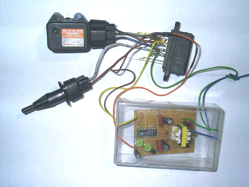
Potentiometer 1 = 203 is for gain = curve angle matching
Potentiometer 2 = 503 is for off-set = level matching
Install - woahla - start :) wah can idle wor :) hahahaha
But signal converter off-set potentiometer need to set to 2.5V and gain
potentiometer to match.
When set to 3.1 volt like AFM for idle cannot :( engine die.
This is because this particular transplant - for unknown reason - needs to idle
high at 1,600 rpm when the battery is freshly plugged back into the ECU. At this
point the AFM Flap's (VS) used to give out around 2.5V
Assuming the ECU
has run in and performs like normal, then setting the signal converter to 3.1
volt will work.
Wah, so near to running open trumpet :) :) :). Can idle, Can rev, but CANNOT maintain
rev :( (i.e. cannot partial throttle hold)
Anyway, give up ........................................... really???
................................ there is another trick :) muah haha ha hahha ha
h ha hha ha ha
Lets see when I'll get mad enough to try the next stupid idea :) muah ha ha hah ahhah ha hahh aa
 Malaysia
Boleh
Malaysia
Boleh