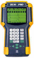
Diagnostic by DCN PRO
Automotive Handheld Scantool / 4 Channels Scope
21 August 2003
Notice how big the thing is? half the size of a notebook, this is huge man!!!!!
details from http://www.datascanlb.com/p3.htm
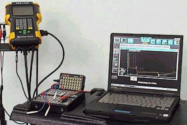
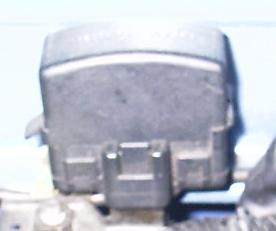
1st connect the Scantool to the car's "diagnostic plug" found in the engine bay. A special converter adaptor have to be used. Please note.
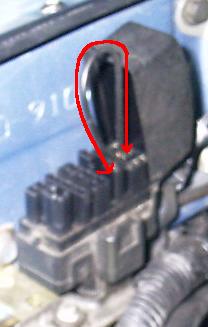
Red color arrows demonstrate one of the many "manual" diagnostic procedure. See Diagnosis System
2nd start the car
3rd turn on the Scantool
Before hand, owners should know exactly what engine or car and most importantly year of manufacture as well.
4th go into Scan mode and it shows: -
| Injector Pulse Width | 2.6 | ms | milliseconds |
| Ignition Advance | 9 | CA | Crank Angle??? |
| ISC duty | 32 | % | Idle Speed Control Valve |
| Engine Speed | 750 | rpm | |
| Air Flow | 3.13 | v | Air Flow Meter's Flap Voltage opening range |
| Coolant temperature | 80 | c | Water Temperature |
| Throttle Position | 0 | % | TPS |
| Vehicle Speed | 0 | km/h | |
| Target A/F Left | 0 | v | Exhaust Sensor |
| A/F Feedback Left | OFF | Exhaust Sensor | |
| Knock Feedback | OFF / ON | ||
| Starter Signal | OFF | ||
| Idle |
ON / OFF |
||
| A/C Signal |
OFF |
||
| O2 feedback |
RICH / LEAN |
Flash between Rich and Lean |
Explanation
Injector Pulse Width - During idling, a figure found between 2.3 to 2.7 ms is good according to the mechanic. The lower the figure the less fuel consumed. Above 2.8 is assumed to be non economical.
For references please see References
For advance details please see Kevin Sullivan's Autoshop101 Technical Articles file h20 EFI#1 system overview.pdf, also h22 EFI#3 fuel delivery and injection control.pdf. These files are OBD level 1 only. Please also refer to other files especially in OBD2.
Small discussion. The fuel delivery is known from injectors size (i.e. cc/min) in this case it is around 290cc/min each and fuel pressure by default factory recommendation is 28psi with vacuum. These will be different from models to models, therefore the statement of "2.3 to 2.7 ms is good" cannot be used as reference, no matter what. Please note.
Ignition Advance - This is suspected to be the distributor timing. The engine manual for this engine recommends between 8 to 12 BTDC. Mine is set to around 9. Increasing or decreasing the timing does not show any difference on the Scantool's display. This is UNUSUAL. According to the mech. all other cars "move" when he adjusted the distributor timing. This is now known to be the case because the Scantool's plug does not contain the IG- pin. See Different Diagnosis
However during engine rev it does show an increase of timing, just not when
the distributor is being adjusted. Therefore anyone going to see this mech.
please check if yours will "move" when the distributor is moved and
let me know. Thanks ![]()
also see files h23 EFI#4 TCCS ignition system.pdf, h39 ignition#1 ignition overview.pdf, h40 ignition #2 electronic spark advance.pdf, h41 ignition#3 distributor and distributorless types.pdf
ISC duty - long story, please refer to Kevin Sullivan's Autoshop101 Technical Articles file h60 Emission#6 - Idle Speed Control System.pdf.
Air Flow - This uses voltage to represent how much air is going into the engine measured by a flap opening ranges. Also see Kevin Sullivan's Autoshop101 Technical Articles file h34 air flow sensors.pdf.
Coolant temperature - when air-cond is off, both cooling fan is off. Coolant temperature increase until 92 then the main cooling fan turned on and at high speed. After temperature reduce to 87 it stopped. The temperature increase again and the cycle repeats. This test proves that the cooling system is working properly.
When the air-cond is turned on, both cooling fan will engage at moderate
speed. This is a self modification made to maintain a lower engine temperature ![]()
So, now it is known on the original dash display at which level is 80c, which
is 87c and which is 92c ![]() no more guessing
no more guessing ![]() one could literary stick his/her
own temperature figures, as this is now calibrated
one could literary stick his/her
own temperature figures, as this is now calibrated ![]()
However this is not truly calibrated, as the Scantool measures the voltage across the sensors, which may be skewed therefore is only a representation by the manufacturer's specification. It can only be taken as an approximate until further comparison with a 3rd party thermometer.
Throttle Position - It is never sure if the TPS is at the correct angle, although the Scantool display 0%, which is theoretically correct for idling. Therefore the TPS is released and turned anti-clockwise and read the changes. The TPS % increases as the TPS angle was moved. Good, working properly. Finally the TPS was returned to it's previous position as it was the correct one. For details please see Kevin Sullivan's Autoshop101 Technical Articles file h33 position sensors.pdf under technical section.
Please note that the Scantool is unable to display negative - 2%.
Target A/F Left - This is the exhaust sensor Air-Fuel-Ratio measurement. Since this is not a wideband high speed ultra accurate sensor, therefore it's accuracy is at question at best. Please read a few files from Kevin Sullivan's Autoshop101 Technical Articles like h37 Sensors#6 - Oxygen / Air Fuel Sensors w/ques.pdf, h44 Fuel System#3 - Close Loop / Fuel Trim w/qu.pdf and more......
The ideal value should be fluctuating above 0.55 and below 0.4 at a rate of faster than 0.8Hz. See Kevin Sullivan's Autoshop101 Technical Articles files........
Notice the Scantool display 0v. This is true until the accelerator is disturbed
for the 1st time after ignition. Well, guess I learn another thing today ![]() Well
if any of you want to let the ECU auto tune??? remember to disturb the accelerator
right after ignition.
Well
if any of you want to let the ECU auto tune??? remember to disturb the accelerator
right after ignition.
The read out / changes is quite sensitive to the little adjustment at the Air Flow Meter's By-pass valve. After this experience, I wouldn't dare to itchy hand and mess with my AFM anymore. Not without further study and measurement equipment assistance.
"bullshxt, I messed with it already :("
The read out is quite stable, never fluctuate. This is very puzzling as the technical articles says it should. The engine manual also says it should. The ECU trouble shooting section did not make sense in the pass, until today. Seems like my O2 is not working properly :( i.e. it is giving feedback but not the correct one.
A/F Feedback Left - This is a funny one. It shows "OFF" or "ON". Once the accelerator is disturbed for the 1st time it will turn "ON" until quick heavy throttle or near full throttle. I wonder what is it doing??? Is this simply telling the user if the ECU is going between closed-loop and open-loop???
Knock Feedback - This only shows "OFF" or "ON". It is
only "ON" when there is TP % above 0. Hmmm cool, not working when
idling ![]() I wonder why???
I wonder why???
Idle - The use of "Idle" indication is very important as not to retard the TPS too much.
If the TPS is retarded too much, the ECU will not know if a light throttle is engaged and hence keep the engine in idling.
The Diagnostic display is unable to show negative TPS percentage. Please note.
This makes the engine reluctant to increase in rpm at light throttle. Think of it as dull response. The degree of "dullness" depends on how bad the TPS is retarded.
This is bad for slow traffic and / or to maintain cruising speed. Imagine at cruising with light throttle and the ECU thinks you're idling. Surely it would not ADVANCE the ignition spark timing firing. But you need speed, so the engine may behave like slow down, increase speed, slow down, increase. This is not consistent and the ECU will get confused.
By using this Idle indication. One can very quickly and accurately adjust the TPS to 0%, then lightly tap / increase the throttle. The display should quickly / immediately show "OFF" instead of "ON"
When this is achieved, you'll have optimum TPS sensitivity.
AC On - At some point testing of the diagnosis requires the air-cond to be turned on. Please see References for details.
O2 Feedback - This is a simple breakdown summary displayed in words of RICH or LEAN from the voltage feedback. It serves as a quick readout for the user. Please see References for details.
So, is this called "Tuning" - by my definition - surely not.
I hope the readers will read everything from Kevin
Sullivan's Autoshop101 Technical Articles and all the questions will be
answered ![]()
ACOUSTICS SECTION AUDIO SECTION CAR SECTION
HOME - Technical Website for Acoustics, Audio and Car
Diagnostic Services available at: -
or
Charges dependent upon different mechanic and services required and negotiations???
 Malaysia
Boleh
Malaysia
Boleh