Rear Axle's Control Arms & Rod
4th August 2004
Part 3
How to set them up? since they are adjustable unit.
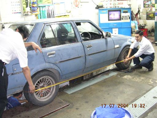
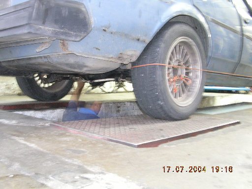
Well, the answer was simple enough. 1st use a string to tie around the four wheels and that would show if there is / are any large discrepancy or erroneous run-outs.
Example about lateral control rod: -
Too short will cause the entire axle to bias right and hence the string will not touch the front right wheel's inner wall.
Too long will cause the axle to bias left, which will cause the front left wheel's inner wall not touched by the string.
Too long will also stress the axle to push forward the left only and cause a toe-in condition on the left rear wheel.
Too short will started to pull the axle backwards on the left and cause a toe-out condition.
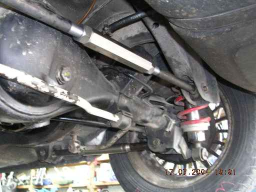
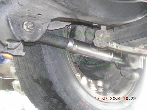
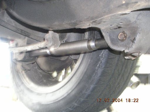
Example about lower control arms: -
Too long on both sides will aim the axle's input downwards and cause stress to the ball joint, as well as suffer power transfer loss as well as vibrations.
Too short on both sides aims the axle's input upwards and causes the same effect as above.
One side too long will cause toe-out, while the other will toe-in.
Likewise for upper control arms.
Hence the settings of these must be referenced to one another in positions, angle, left to right off-set bias, overall toe in or out and axle's input angle for efficient power transfer.
One very big mistake was made previously which is the front wheels were not aligned properly. Therefore make sure the fronts are properly set in terms of: -
Castor forward maximum and same angle on both side (should be around 0.5 degrees max)
Camber same on both side - which ever degrees you like (between 0.5 to 1.5 is acceptable - depends on requirements)
Toe - depends on requirement. Generally toe-in, but I was advised toe = zero to prevent tyre inner wear when using high camber beyond 2 degrees.
However, chassis which experienced severe accident / collision will suffer slightly. This will be a bad penalty :(
Please remember to use a tap measure to perhaps cross measurement between front and rear of each left and right as well as front left to rear right and front right to rear left. Find the center point and make sure that it is square or rectangular.
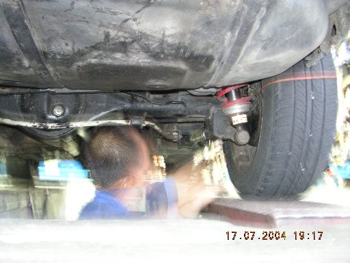
Notice the lower control arm is nearly flat and not pointing the axle downward. Imagine when the car experience a bump and SINKs downward. The axle / car will experience momentarily "AFLOAT" and has no grip. The solution is to make a custom bracket to attach onto the existing mount at the bottom of the axle and have new holes / positions so that the lower control arm will remain pointing the axle downwards even during a SINKing maneuver.
 Malaysia
Boleh
Malaysia
Boleh